# Rectifier Filter Power Supply Board Amplifier Dual Power PCB Bare Board
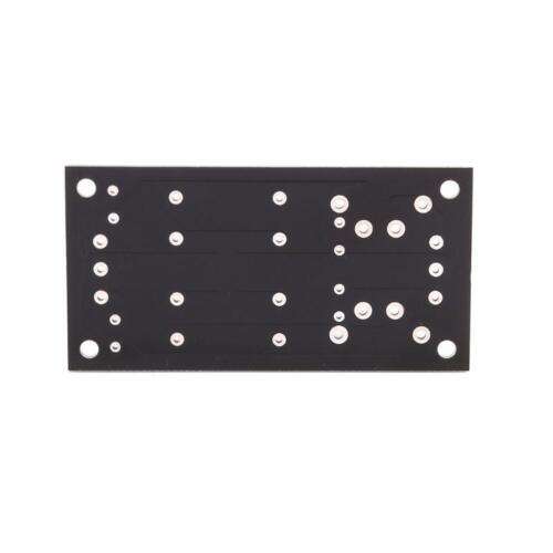
A Rectifier Filter Power Supply Board Amplifier Dual Power PCB Bare Board is a printed circuit board (PCB) designed to convert alternating current (AC) electricity to direct current (DC) electricity. It is used in various electronic devices, including amplifiers, power supplies, and audio equipment.
## Benefits:
– Provides a stable and reliable DC power supply for electronic devices.
– Improves the performance and efficiency of electronic devices.
– Protects electronic devices from damage caused by voltage spikes and fluctuations.
– Compact and lightweight design for easy installation in tight spaces.
## Features:
– Dual power supply design with separate positive and negative voltage rails.
– Rectifier bridge to convert AC to DC.
– Filter capacitor to remove AC ripple from the DC output.
– Voltage regulator to provide a stable and regulated DC output.
– Heat sink to dissipate heat from the voltage regulator.
– Terminal blocks for easy connection of input and output wires.
## Specifications:
– Input voltage: AC 110-240V 50/60Hz
– Output voltage: DC ±15V, ±12V, ±9V, ±5V (selectable)
– Output current: 2A max
– Dimensions: 110mm x 68mm x 25mm
– Weight: 140g
## Key Usage Points:
– Easy installation with terminal blocks for input and output connections.
– Durable construction with high-quality components for long-lasting performance.
– Color options available to match the aesthetics of different electronic devices.
## Relevant External Links:
– [How to Build a Rectifier Filter Power Supply Board](https://www.electronicshub.org/how-to-build-a-rectifier-filter-power-supply-board/)
– [Power Supply PCB Design Guidelines](https://www.pcbway.com/blog/Power_Supply_PCB_Design_Guidelines.html)
– [Troubleshooting Rectifier Filter Power Supply Boards](https://www.homemade-circuits.com/2014/04/troubleshooting-rectifier-filter-power.html)